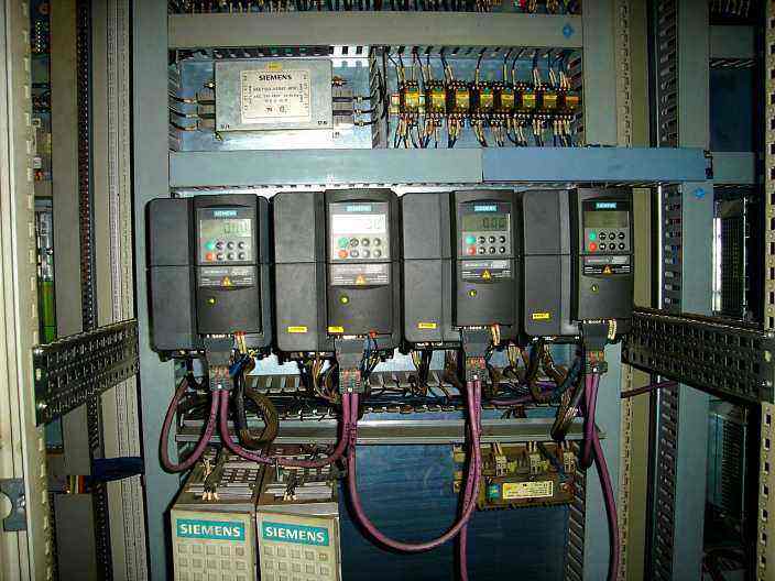
The frequency changer hardware detection method:
1:static test
1.1, test rectifier circuit
Find the P terminal and N terminal of the internal DC power supply of the inverter, adjust the multimeter to the resistance X10 file, the red indicator bar to P, and the black indicator bar to R, S, T respectively. There should be about several tens of euros of resistance. And basically balanced. Instead, the black bar is connected to the P terminal. The red bar receives R, S, and T in turn and has a resistance close to infinity. Bring the red bar to the N-side and repeat the above steps to get the same result. If you have the following results, you can determine that the circuit has abnormal, A. Three-phase unbalanced resistance, it can explain rectifier bridge failure. B. When the red bar is connected to the P terminal, the resistance is infinite, and it can be concluded that the rectifier bridge fault or starting resistor has failed.
1.2, test inverter circuit
The red table rod is connected to the P-side. The black table rods are connected to U, V, W, respectively. There should be several tens of euros of resistance, and the resistance of each phase is basically the same. The reverse phase should be infinite. Connect the black meter to the N terminal. Repeat the above steps to obtain the same result. Otherwise, you can determine the failure of the inverter module.
dynamic test
After the static test result is normal, the dynamic test can be performed, that is, the power test machine is connected. Before and after power on, you must pay attention to the following points:
2.1. Before powering on, make sure whether the input and output of the main circuit of the power supply are reversed. If the input voltage is incorrect, if the input and output are reversed or the 380V power supply is connected to the 220V inverter, a bomber will appear. Capacitors, varistors, modules, etc.)
2.2. Check whether each interface of the inverter has been correctly connected and whether the connection is loose. If the connection is abnormal, it may cause the inverter to malfunction. In severe cases, it may cause explosion and other situations.
2.3. After the power is turned on, the fault display content is detected, and the fault and cause are initially determined.
2.4. If the fault is not displayed, first check whether the parameters are abnormal, then restore the parameters to the factory settings, start the inverter with no load (motor not connected), and test the U, V, W three-phase output voltage. If there is a lack of phase, three-phase imbalance, etc., the module or the driver board is faulty.
2.5. Load test under normal output voltage (no phase loss, three phase balance). When testing, it is best to be full load test.
The inverter's common fault
At present, what people call the AC speed control system mainly refers to the frequency conversion speed control system of the AC power motor. The frequency conversion speed control system is superior to the DC drive in that it is used as the preferred transmission scheme in many applications. The speed control performance is basically similar to the DC speed control. However, when using the inverter, the maintenance work is more complicated than that of the DC. In the event of a failure, it is difficult for the general electrician of the company to deal with it. Here, a simple analysis is made of the causes of the common faults of the inverter and the methods of handling.
1, parameter class fault:
Whether the inverter can meet the requirements of the drive system in use, the parameter setting of the inverter is very important. If the parameters are not set correctly, the inverter will not work properly.
In general, the factory has a default value for each parameter. These parameters are called factory values. In the case of using these default parameter values, the user can normally operate in a panel operation, but the panel operation does not meet the requirements of most drive systems. Therefore, before the user correctly uses the inverter, the inverter parameters must be set, mainly from the following aspects:
(1) To confirm the motor parameters, the inverter sets the motor power, current, voltage, rotation speed, and maximum frequency in the parameters. These parameters can be obtained directly from the motor nameplate.
(2) The control method adopted by the inverter, ie, speed control, torque control, PID control or other methods. After selecting the control method, it is generally necessary to perform static or dynamic identification according to the control accuracy.
(3) Set the start mode of the inverter. Normally, the inverter is set to start from the panel at the factory. The user can select the start mode according to the actual situation, and can use the panel, external terminals, and communication methods.
(4) For the selection of a given signal, there are many ways to set the frequency of the inverter. It can be given by the panel, externally given, external voltage or current given, and communication method given. Of course, the frequency of the inverter is given. It can also be the sum of one or more of these methods. After correctly setting the above parameters, the inverter can basically work normally. If you want to get better control effect, you can only modify the relevant parameters according to the actual situation.
Handling of parameter setting faults: Once a parameter setting fault occurs, the inverter cannot operate normally. Generally, the parameters can be modified according to the instructions. If not, it is best to restore all parameters to their factory values and then reset them according to the above steps. For each company's inverter, the parameter recovery method is not the same.